Articles

Antenna Connector Types: Choose the Right Specifications to Maintain High-Quality Signal Transmission!
26-09-15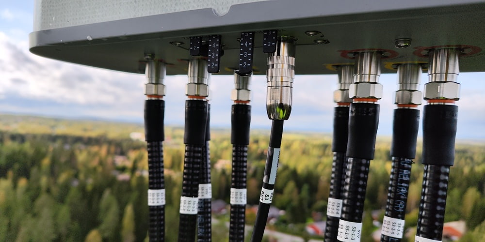
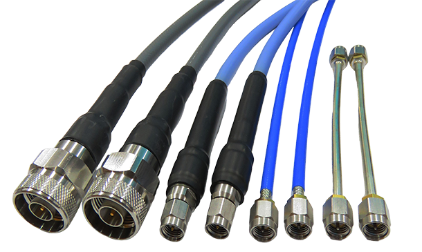
An antenna connector is an important component in RF systems that connects antennas and coaxial cables. It transfers RF signals from equipment to antennas or carries signals received by antennas to receivers; therefore, selecting the right specifications is essential to maintaining high-quality signal transmission and avoiding unnecessary loss and interference. This article introduces common antenna connector types, factors affecting signal transmission, and considerations for selection and installation.
What Is an Antenna Connector? Understanding Common Specifications and Applications
Antenna connectors are primarily installed at the ends of coaxial cables or RF equipment. They transmit RF signals in shielded environments, ensuring stable impedance matching performance and minimizing signal loss. Antenna connectors also provide both electrical continuity and mechanical fastening and, while withstanding mechanical stress, maintain signal transmission integrity.
〈Related Articles: What Are RF Connectors?〉
SMA Antenna Connector
An SMA antenna connector is a widely used compact threaded RF coaxial connector, featuring a threaded locking structure, long service life, superior performance, and high reliability, with an operating frequency range from DC to 18 GHz (precision versions up to 26.5 GHz), commonly used in microwave equipment, Wi-Fi modules, and GPS receivers, as well as RF circuits in digital communications equipment applications.
〈Related Articles: SMA Connectors - The Most Common RF Connectors〉
〈Related Articles: Microwave Technology Principles and Applications〉
BNC Antenna Connector
BNC antenna connectors are available in 50 Ω and 75 Ω impedance versions, with maximum frequencies of 4 GHz and 2 GHz, respectively. They are RF coaxial connectors featuring a bayonet-lock mechanism, offering quick connection and easy operation; they only need to be rotated approximately one-quarter turn to lock or unlock, making them suitable for applications requiring frequent insertion and removal, such as test instruments, CCTV and telecommunications equipment.
〈Related Articles: What is RF Microwave? Mastering Technology Applications and Key Components for More Stable Wireless Communication!〉
TNC Antenna Connector
A TNC antenna connector is a BNC antenna connector with an enhanced threaded design, replacing BNC's original bayonet coupling with a threaded connection. Therefore, in vibrating environments, TNC offers superior resistance to loosening and more stable contact performance and is commonly used in outdoor communication equipment and vehicle-mounted antenna systems, or in applications requiring high stability in industrial environments.
N-Type Antenna Connector
An N-Type antenna connector is a threaded RF connector. It is larger than SMA connectors but offers greater mechanical strength, vibration resistance, and environmental adaptability. Its operating frequency range extends from DC to 11 GHz (up to 18 GHz for precision versions), and it is commonly used for base station antennas and high-power RF amplifiers, as well as outdoor long-distance communications. It is a higher quality option for 50 Ω systems among antenna cable choices.
〈Related Articles: What is an N Connector and How Does It Work?〉
Why Do High Quality Antenna Connectors Affect Signal Transmission Performance?
Antenna connectors are passive components in RF transmission lines; poor-quality or poorly designed connectors can alter the electrical characteristics of transmission lines and degrade communication quality or cause data loss. The following introduces three factors affecting signal transmission stability and efficiency.
Low Insertion Loss and Signal Attenuation
Insertion loss is the energy lost as a signal passes through a connector. The lower the value, the more completely the energy is retained. High-quality antenna connectors use superior conductor materials, such as gold-plated contacts, and precision structural design to keep contact resistance at extremely low levels and reduce energy loss. In contrast, inferior connectors produce greater insertion loss, causing significant signal attenuation.
Good Impedance Matching, Low Reflection, and Low VSWR
VSWR (Voltage Standing Wave Ratio) is an important metric; when the antenna connector impedance matches the system, RF energy can be transmitted smoothly. If the impedance is mismatched, part of the signal is reflected to form standing waves, which not only reduces transmission efficiency but may also damage the transmitter circuitry.
Effective Shielding Structure and Low Noise
The center and outer conductors of an RF coaxial connector together form the transmission path for RF signals, with the electromagnetic field between them transmitting RF energy, while the outer conductor also provides a signal return path and electromagnetic shielding. Especially in industrial environments or high-density electronic equipment, effective shielding design is necessary to prevent signal interference and distortion.
How to Select the Right Antenna Connector?
When selecting an antenna connector, it is essential to evaluate equipment specifications, impedance, frequency, power, and other factors to avoid hardware damage caused by incompatible specifications. The following outlines several key selection considerations to help businesses quickly identify suitable antenna connectors.
Check the Equipment and Antenna Connector Models
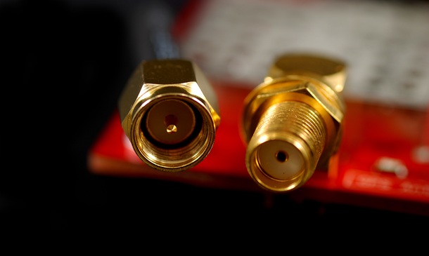
Check the equipment-side antenna connector type. Inspect whether the center contact is a metal pin or socket. Especially when distinguishing SMA from RP SMA, do not determine it solely by whether the threads are internal or external. The internal conductor structure must be the primary criterion. Otherwise, incorrect matching may cause the antenna connector to fail to tighten securely or make poor contact, affecting signal transmission.
Confirm Impedance
The characteristic impedance of coaxial cables and antenna connectors is generally classified as 50Ω and 75Ω. They are designed for different purposes and must not be mixed. 50Ω balances power handling and attenuation and is suitable for wireless communications; 75Ω is designed to minimize signal attenuation and is suitable for video transmission.
〈Related Articles: What Are Satellite Coax Cable Connectors? A Complete Guide to Characteristics, Specifications, and Applications!〉
Antenna Connector Impedance Comparison Table
| Specification | 50 Ohms (50Ω) |
75 Ohms (75Ω) |
|---|---|---|
| Advantages | Balancing Energy Transfer and Attenuation | Extremely Low Signal Transmission Attenuation |
| Applications |
|
|
| Risks of Damage from Mixing | Forcing a 50 ohm male connector into a 75 ohm female jack (such as a BNC connector) will, because the 50 ohm center pin has a larger diameter, directly expand and damage the 75 ohm receptacle, resulting in permanent open-circuit damage, and causing severe signal reflections. | |
Operating Frequency Range
Different antenna connector designs each have a maximum supported frequency; for example: BNC is generally suitable for frequencies below 4GHz. Standard SMA connectors can reach 18GHz, while more advanced precision connectors such as 2.92mm support frequencies of 40GHz and above. Select the appropriate antenna connector based on the system's actual operating frequency band.
〈Related Articles: What Is High Frequency? High Frequency Features and Applications!〉
Compatible Cable and Power Requirements
The antenna connector's dimensions must match the outer diameter of the coaxial cable, and if the transmitting equipment has high power, select N type connectors, which are larger and provide better heat dissipation and high voltage resistance. This prevents high power transmission from overheating and deforming the dielectric material inside the connector.
〈Related Articles: How to Choose a Satellite Connector? A Guide to Satellite Coax Connector Specifications, Installation, and Causes of No Signal〉
Antenna Connector Installation Steps at a Glance!
Installing an antenna connector on a coaxial cable requires precise handling. The following are the installation steps for a standard crimp connector:
- Cable Stripping Preparation: Use a dedicated coaxial cable stripper according to the antenna connector's manufacturer-specified dimensions to precisely strip the outer jacket, metal braided shield, and inner dielectric insulation layer, exposing the center conductor.
- Connect the Center Pin: Fit the connector's center pin onto the exposed copper conductor, then use a dedicated crimping tool to secure the center pin, or solder it with a soldering iron. Ensure that the joint has no cold solder joints or incomplete soldering.
- Install the Housing and Crimp Ring: Evenly fold back the coaxial cable's braided shield, slide the connector body housing on so that the braid tightly covers the outside of the metal tube at the connector's rear end, and finally install the metal retaining ring (Crimp ring).
- Crimping and Securing: Using a hex crimping tool, firmly crimp the metal retaining ring, ensuring that the antenna connector and cable are securely joined, with adequate pull resistance.
- Testing and Verification: After installation, be sure to use a multimeter to check for a short circuit between the center pin and the housing, and use a network analyzer as needed to verify that the impedance and VSWR values are within specifications.
Antenna Connector Frequently Asked Questions
Q1. Can adapters be used to resolve antenna connector mismatch issues?
Yes, various SMA-to-BNC, N-type-to-SMA and other adapters are available on the market, but it is important to understand that each additional adapter introduces extra insertion loss and impedance discontinuities; for high-frequency or weak-signal applications, the use of adapters should be avoided or minimized.
〈Related Articles: How to Choose the Right N Type to SMA Adapter for Your Project〉
〈Related Articles: Phased Array Antenna Connectors: High-Frequency Packaging & Phase Control〉
Q2. Is there a torque limit when installing SMA connectors?
Yes, SMA antenna connectors require appropriate torque when connected, and a dedicated torque wrench is generally recommended. The recommended torque for brass is approximately 0.3 to 0.6 N·m, and for stainless steel it is 0.8 to 1.1 N·m. Under-tightening can result in poor connector contact, while over-tightening can permanently damage the internal dielectric material and metal contacts.
Q3. How can the male and female SMA antenna connectors be distinguished?
An SMA male connector has a pin-shaped center conductor and internal shell threads, whereas an SMA female connector has a socket-shaped center contact and external shell threads. However, the RP SMA (Reverse Polarity) version reverses this configuration, so when purchasing, be sure to carefully verify the equipment-side specifications.
Q4. Can 50Ω and 75Ω connectors with the same appearance be used interchangeably?
Although some models have identical external dimensions, they are not recommended for use interchangeably. Impedance mismatch may cause severe signal reflections, increasing VSWR and reducing transmission efficiency. More seriously, the center pin of a 50Ω male connector is thicker, and forcibly inserting it into a 75Ω female connector may cause mechanical damage.
〈Related Articles: The Ultimate Guide to SMA Plug Connector Types and Specifications〉
〈Related Articles: High Performance Female SMA Connector: What You Need to Know!〉
Conclusion
Although antenna connectors are relatively small components in RF systems, they can significantly affect signal quality, so when selecting a model, it is essential to consider model compatibility, impedance specifications, frequency range, and mechanical environment requirements to ensure that high quality antenna connectors deliver their intended performance.
If you are looking for antenna connectors that meet industrial-grade standards and support high-frequency, high-power applications, Huang Liang Technologies offers RF connectors in a wide range of specifications and customized cable assembly services, widely used in military, defense and aerospace, satellite communications, and other fields, helping businesses quickly deploy stable and reliable signal transmission systems. Please contact us for more information.
〈Related Articles: Recommended RF Connector Manufacturers: 5 Key Factors to Consider Before Partnering for a Major Equipment Performance Upgrade〉