Articles

Phased Array Antenna Connectors: High-Frequency Packaging & Phase Control
26-08-14
The rapid development of Low Earth Orbit (LEO) satellites and Electronically Scanned Array (ESA) radar has pushed the hardware design space to its limit. General phased array systems typically contain 64 to 128 or more antenna paths, each requiring independent signal processing, beamforming, and RF transmission. Traditional independent coaxial cables can no longer meet space and weight constraints.
As the core technology of modern communication and radar systems, miniaturized and high-density phased array antenna connectors can meet current technical requirements through high-frequency microwave transmission and precise phase control.Phased Array Antenna Connectors Break through Space Constraints, Upgrading PCB Optimization!
Phased array antenna connectors feature multi-pin and high-density characteristics. They do not rely on mechanical motor rotation but instead electronically control the signal phase of each antenna unit, reducing RF PCB area, optimizing complex internal layouts to change the direction of beam transmission and reception. Therefore, highly integrated internal signal routing is required to achieve high-resolution beam control.
Moving from 3D Brick Architecture to 2D Planar Packaging
In the past, antenna arrays mostly used 3D brick configurations, where internal transceiver modules, power amplifiers, and phase shifters had to be connected via numerous coaxial cables and large adapters, resulting in a bulky size and very high manufacturing costs. Currently, the phased Array Antenna connector design has shifted to a 2D planar design, introducing Surface Mount Device (SMD) and Antenna-in-Package (AiP) technologies to integrate antenna units and RF chips onto a single PCB or stacked PCBs, making RF systems flatter and lighter.
〈Related Articles: What is RF Microwave? Mastering Technology Applications and Key Components for More Stable Wireless Communication!〉
Mixed-Signal Transmission Technology and Open-Pin-Field Arrays
In previous RF systems, digital signals, power, and analog RF signals required their own independent connectors, occupying a large amount of PCB area. To solve this problem, the system introduced open-pin-field array connector designs, allowing engineers to route single-ended RF signals, differential digital signals, and high-current power paths within the same connector structure, simplifying hardware architecture and reducing the number of physical components.
〈Related Articles: What are RF Connectors?〉
Phased Array Antenna Connector Specifications and Standards at a Glance
When evaluating components for phased array antenna connectors, the following specification data must be strictly reviewed based on the system's operating bandwidth and impedance matching requirements.
Phased Array Antenna Connectors Specifications and Standards Comparison Table
| Specification Item | Common Standards and Data | Impact on System Design |
|---|---|---|
| Pin Pitch (Pitch) |
0.635 mm or lower | Determines the routing density of the circuit board; smaller pitch saves more space. |
| Frequency Range | Ku-band (12-18 GHz) to Ka-band (26-40 GHz) | Affects whether the connector can support lossless high-bandwidth satellite data transmission. |
| System Impedance | Single-ended 50 ohms, Differential 100 ohms | Impedance mismatch leads to signal reflection and severe energy loss. |
| Allowable Offset (Misalignment) |
Radial ±3°, Axial 0.25 mm (0.010 inches) | Affects assembly tolerance, ensuring contacts do not detach under vibration. |
| Crosstalk Isolation (Crosstalk) |
Reaches -63 dBc at 8 GHz | Prevents interference between adjacent high frequency channels, maintaining signal purity. |
(Swipe left or right to view the full table.)
Signal Integrity and Phase Stability of Phased Array Antenna Connectors
In the Ku and Ka bands of satellite communications, maintaining extremely low insertion loss and preventing phase deviation are the basic thresholds for hardware design. Even minor mechanical stress or temperature changes could cause serious errors in beam pointing.
High-Speed Switching Requirements for Electronic Beam Scanning
Low Earth Orbit (LEO) satellites must fly at extremely high speeds of approximately 7.8 kilometers per second to counteract gravity and ensure their orbit does not deviate. Therefore, in addition to transmitting high frequency RF signals, phased Array Antenna connectors must maintain extremely low latency for digital control signals to support real-time electronic beam switching and dynamic tracking. If the signal integrity of the connector is insufficient, it may cause beam misalignment during switching, leading to data loss.
〈Related Articles: Top 5 Key Indicators for Choosing the Right RF Company to Boost Performance〉
Modular Design Solves PCB Warpage and Yield Issues
A large electronic scanning array system contains hundreds to thousands of antenna units. If all RF circuits are concentrated on a single large circuit board, board warpage is likely to occur during high temperature pressing, resulting in extremely low production yields. Through phased array antenna connectors, R&D personnel can decompose large antennas into multiple small, standardized sub-modules, reducing mechanical stress and maintaining stable system yield and maintainability.
Blind Mating and Tolerance Compensation in High Frequency Bands
Under high-frequency transmission, mechanical assembly tolerances between circuit boards can severely affect the VSWR, leading to signal attenuation. Therefore, it is essential to adopt a "Bullet" adapter design for SMP and SMPM board-to-board connectors in high frequency applications. This allows the equipment to absorb axial and radial physical displacements during blind-mate assembly or when encountering severe thermal expansion and contraction, maintaining stable RF path length and phase consistency.
Temperature Differences, Vibration, and Vacuum Challenges
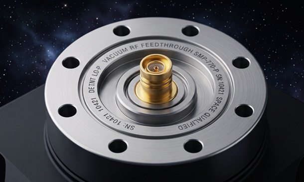
During launch and in-orbit operation, phased array antenna connector systems must withstand high-intensity vibrations from the launch vehicle as well as extreme temperatures in the space environment. In addition, to adapt to high vacuum environments, the connector shells and internal insulating materials must strictly comply with low outgassing specifications to prevent plastic materials from releasing volatile organic molecules that could condense on the surfaces of sensitive optical or RF sensors.
Points to Note When Selecting Phased Array Antenna connectors
When selecting phased array antenna connectors and components, it is recommended to conduct a comprehensive evaluation based on the following four technical aspects.
Electrical Performance
Confirm whether the bandwidth supported by the phased array antenna connectors fully covers the Ku or Ka bands. It is necessary to review the S-parameter test reports provided by the supplier to examine return loss, insertion loss under high-frequency conditions, and crosstalk isolation performance between adjacent channels.
Mechanical Life and Durability
Confirm the guaranteed mating cycle standards for the phased array antenna connector design. For high vibration aerospace applications, it is necessary to verify whether the gold-plating thickness and normal force design of the terminal contact points are sufficient to resist the risk of fretting corrosion and poor contact caused by long term vibration.
Thermal Management
High-density multi-channel transmission and peripheral RF power amplifiers generate concentrated local heat. It is necessary to review the current-carrying capacity and derating curve of the phased Array Antenna connectors, and reserve sufficient thermal vias and grounding plane area during PCB layout to allow thermal energy to be effectively dissipated.
Total Cost
Although high end and high frequency phased array antenna connectors have higher initial implementation costs, they offer the advantages of hybrid transmission and high density, which can reduce the number of independent components on the circuit board and simplify wiring and assembly processes. Evaluated at the system level, this can reduce overall debugging time, maintenance, and manufacturing costs.
Understanding Typical Applications of phased Array Antenna connectors
Phased array antenna connectors are widely used in high end communications and radar fields with strict restrictions on spatial dimensions and weight due to their miniaturization and high frequency performance features.
Active Electronically Scanned Array Antennas (Phased Array Antennas)
Phased array antenna connectors are applied in various active electronically scanned array systems, enabling the integration of high density transceiver modules within limited space. They support 5G MIMO, military radar, and multi-channel signal transmission, balancing high speed, signal stability, and extremely low-loss performance.
Low Earth Orbit and Medium Earth Orbit Satellites (LEO/MEO Satellites)
In LEO and MEO satellite systems, phased Array Antenna connectors are commonly used for data transmission between the RF front-end modules and the core digital signal processing boards within the satellite payload. Due to their vibration resistance and low outgassing characteristics, they can maintain stable connections for high frequency signals, meeting the lightweight requirements of space environments.
Unmanned Aerial Vehicles (UAVs)
In UAVs and avionics equipment, phased array antenna connectors can support the transmission of large volumes of data from high-resolution optical or RF sensors in high-altitude environments, while simultaneously meeting the hardware requirements for Synthetic Aperture Radar (SAR) tracking and beyond-visual-range communication systems.
Common Q&A for Phased Array Antenna Connectors
Q1. What is an Open-Pin-Field Array Connector?
Open-Pin-Field Array Connectors allow hardware engineers to customize the signal pin distribution within the same connector. They can transmit analog RF signals, differential digital signals, and power, and enhance PCB routing flexibility while save space.
Q2. How Do Phased Array Antenna Connectors Solve Phase Shift Issues at High Frequencies?
This is primarily achieved through a precision-machined bullet adapter structure. It physically absorbs axial and radial mechanical assembly tolerances. In environments with severe vibration and temperature cycling, it maintains consistent signal transmission path lengths and impedance across all channels, preventing beam divergence and phase distortion.
Q3. Why Do Aerospace Applications Using Phased Array Antenna Connectors Require Low-Outgassing Materials?
In the high-vacuum environment of space, ordinary plastics and adhesives continuously release volatile organic molecules. Once these gas molecules condense on radar array surfaces or optical sensors, they cause signal interference and hardware damage. Therefore, aerospace applications must use special engineering plastics and packaging materials that have been verified for low outgassing.
Q4. How Does The Choice of Connector Differ When Upgrading A System to Ku or Ka Bands?
Higher signal frequencies mean shorter wavelengths, which places extremely strict requirements on impedance matching and VSWR within the connector. When upgrading to the Ka band, precision microwave connectors with tighter internal mechanical tolerances and support for higher cutoff frequencies (usually above 40 GHz) must be selected, such as SMPM or specially designed high-frequency array connectors.
〈Related Articles: Microwave Technology Principles and Applications〉
Q5. How Do You Determine The Appropriate Height?
The stack height of board-to-board connectors must be determined based on the system's heat dissipation requirements, the internal space constraints of the metal shielding enclosure, and the height of adjacent surface-mount components. Currently, phased array antenna connectors on the market typically provide flexible stack-height options ranging from 5 mm to 16 mm or even higher for hardware engineers to match.
Conclusion
In the fields of satellite communications and aerospace radar, the miniaturization, modularization, and high frequency operation of RF systems are already frequently used technologies. Choosing suitable phased Array Antenna connectors can save circuit board space and allow equipment to maintain signal integrity and phase accuracy in harsh space environments.
Huang Liang Technologies possesses extensive experience in precision machining and manufacturing capabilities for high-frequency connectors. We can provide reliable customized solutions for high-tech communication applications such as aerospace. From design, module analysis, and assembly to performance testing, we strictly control every step of the manufacturing process. If your enterprise has any needs, please contact us, and our professionals will assist in building the most suitable system architecture.