Articles

Hermetic RF Feedthrough Applications: Maintaining Stable Signal Integrity in Extreme Environments
26-09-14
In ultra-high-vacuum (UHV), high-pressure, and extreme-temperature environments, transmitting RF signals into an isolated chamber without signal loss presents a significant engineering challenge. RF feedthroughs provide both high frequency signal transmission and hermetic physical isolation, enabling RF signals to be reliably transmitted from the atmosphere into a vacuum or sealed chamber. This article will provide a detailed introduction to the sealing principles of RF feedthroughs, specification and material selection, and applications in semiconductor equipment, aerospace electronics, and other fields.
RF Feedthroughs and Hermetic Sealing Principles
RF feedthroughs can tightly seal the gaps between insulators and metal housings. Technologies include glass-to-metal seals and ceramic-to-metal seals. During manufacturing, the insulation of material and metal housing are bonded together through high-temperature sintering, thereby isolating the chamber from ambient air and moisture and maintaining extremely low pressure or vacuum inside.
For high-voltage and high-power RF requirements, a combination of alumina ceramic and polytetrafluoroethylene (PTFE) is often used in structural designs, which can withstand high voltages, maintain a stable dielectric constant, and effectively resist mechanical vibration and long-term aging.
〈Related Articles: What is RF Microwave? Mastering Technology Applications and Key Components for More Stable Wireless Communication!〉
RF Feedthrough Specifications and Materials: How to Choose the Right Materials?
Material selection directly impacts the long-term reliability of hermetic RF feedthroughs. A mismatch in the coefficient of thermal expansion (CTE) between dissimilar materials is the primary cause of hermetic seal failure. To mitigate thermal expansion stress, Kovar is commonly chosen for the housing and center conductor because of CTE closely matches that of borosilicate glass or alumina ceramics, effectively minimizing the stress generated during high-temperature sintering and thermal cycling.
Although stainless steel has superior corrosion resistance, its coefficient of thermal expansion differs substantially from that of glass or ceramic. If sealed directly, a specialized compression-seal design is required to compensate for thermal stress.
RF Feedthrough Leak Rate and VSWR
When evaluating RF feedthroughs, hardware R&D engineers place the greatest emphasis on two parameters: helium leak rate and voltage standing wave ratio (VSWR). These parameters have a trade-off in physical design: increasing the area or thickness of insulating contact surfaces to achieve maximum hermeticity may disrupt the geometric proportions of the coaxial structure, causing impedance to deviate from 50Ω and increasing VSWR. However, through precise materials science and electromagnetic simulation, modern feedthroughs can now achieve both.
Low Leak Rate
Leakage through any opening, minute gap, or outgassing pore must be minimized to prevent gas or moisture ingress from damaging internal components or degrading performance. Under high-reliability standards, the helium leak rate of RF feedthroughs is typically controlled at<1×10^-8 atm·cc/sec. Some ceramic coaxial feedthroughs developed for high-energy physics experiments and particle accelerators can even suppress vacuum leak rates to below 1×10^-13 Pa·m³/s, meeting the requirements of extreme ultra-high-vacuum systems.
〈Related Articles: What are RF Connectors?〉
Characteristic Impedance
Characteristic impedance preserves the integrity of RF signals, and stability within the RF feedthrough is maintained through precise calculations of the center conductor diameter and insulator dielectric constant, typically set strictly at 50Ω. At interfaces between dissimilar materials, if impedance matching is absent, impedance discontinuities can easily occur, causing severe signal distortion and reflection.
Low Voltage Standing Wave Ratio (VSWR)
A low VSWR indicates very low reflection loss during signal transmission, allowing RF energy to effectively pass through the isolation interface, and through precision center conductor machining and controlled dielectric geometry, modern hermetic feedthroughs can offset parasitic capacitance introduced by enhanced sealing structures and reliably maintain a 50Ω characteristic impedance across a wide frequency range, preventing VSWR degradation.
RF Feedthrough Performance Comparison Table
| Performance Metric | Design Considerations and System Impact |
|---|---|
| Helium Leak Rate (He Leak Rate) |
Prevents gas permeation and maintains a high vacuum in the chamber, relying on perfect CTE matching. |
| Characteristic Impedance (Impedance) |
Must be maintained through precise calculations of the center conductor diameter and insulator dielectric constant to avoid signal distortion. |
| Voltage Standing Wave Ratio (VSWR) |
To reduce reflection loss of high frequency signals, overly reinforced sealing structures without geometric optimization can easily lead to VSWR degradation. |
RF Feedthrough Electrical Withstand and High-Power Design
For high-energy physics accelerators or high-power RF modules, electrical withstand capability is also an important factor to consider. In vacuum environments, under the influence of Paschen's Law, the gas breakdown voltage at certain pressures is significantly reduced; therefore, the RF feedthrough insulation design and discharge protection require special treatment.
Voltage Withstand and Insulation Resistance
To prevent breakdowns during high-power transmission, the RF feedthrough must meet extremely high insulation specifications. Typical commercial- and military-grade specifications require a withstand voltage of≥ 300 V, and the insulation resistance of a single-pin structure should be≥ 2000 MΩ. Materials such as high-purity glass or alumina ceramic not only provide low dielectric loss but also maintain stable electrical insulation under high-voltage conditions.
〈Related Articles: Understanding Hermetic Sealing Technology and Hermetic Connectors in RF Applications〉
Stepped Transition Design
For high-power, high-voltage coaxial vacuum feedthroughs, a stepped transition configuration is often used, using precise 3D electromagnetic simulation to smoothly transition between regions with different dielectric constants, for example: transitioning from air to glass and then to vacuum effectively eliminates electric-field concentration while maintaining a stable characteristic impedance of 50 Ω.
RF Feedthrough Interfaces Require Attention! Customization Reduces Assembly Tolerances
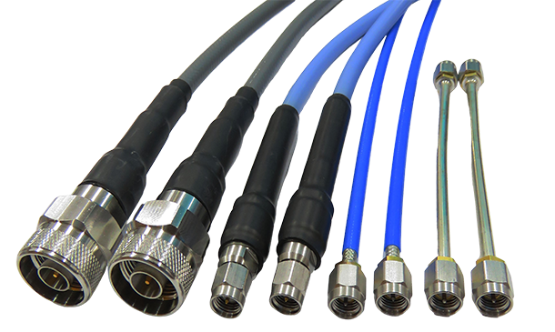
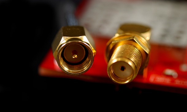
RF feedthrough interfaces on both sides affect assembly convenience and microwave signal continuity. Common external RF interfaces include SMA and SMP, as well as miniature connectors for millimeter-wave bands. In addition to RF connectors, Huang Liang Technologies provides high-rigidity CNC machining capabilities. For RF and microwave coaxial connectors and adapters, customized designs help reduce assembly tolerances, maintain impedance matching, and improve VSWR stability, and support broad applications in semiconductor, defense and aerospace, military, and communications fields.
〈Related Articles: Top 5 Key Indicators for Choosing the Right RF Company to Boost Performance〉
RF Feedthrough Applications in Semiconductor, Aerospace, and Other Fields
RF feedthroughs are widely used in industrial applications and scientific research requiring strict environmental isolation and RF signal transmission. The following sections introduce several fields where this technology is applied.
Semiconductor Vacuum Chambers
Semiconductor processes, such as sputtering, etching, or chemical vapor deposition (CVD), must be performed in highly controlled vacuum and plasma environments. RF feedthroughs are responsible for stably transmitting high-frequency RF energy from the external atmospheric environment into the chamber to excite plasma. Any minor hermetic seal failure that allows atmospheric infiltration, or signal attenuation causing unstable power output, can result in wafer process scrap.
Aerospace & Satellites
In aerospace and satellite radar and avionics equipment, hardware must withstand the severe vibrations of launch and the extreme temperature fluctuations caused by the day-night cycle in space. RF feedthroughs are lightweight, resistant to thermal shock, and compliant with military-grade hermeticity standards, enabling high-frequency communication modules to operate reliably in space.
〈Related Articles: Phased Array Antenna Connectors: High-Frequency Packaging & Phase Control〉
〈Related Articles: What are satellite coax cable connectors? A complete guide to characteristics, specifications, and applications!〉
Demanding Military Detection Applications
Military radar and detection equipment are often deployed in high-humidity, salt-spray, or deep-sea high-pressure environments, requiring the use of robust glass-to-metal or ceramic-to-metal seals to completely isolate moisture and corrosive media, protecting sensitive internal RF transceiver circuits from penetration that could cause short circuits, corrosion, or frequency drift, thereby ensuring long-term stable operation.
Telecommunications Communications
With the widespread adoption of 5G and high-frequency millimeter-wave communications infrastructure, outdoor base station antenna feedthroughs require greater weather resistance. Low-loss, low-VSWR designs enable microwave signals to maintain excellent transmission efficiency and stability in harsh conditions such as high humidity, high temperatures, and salt spray, reducing signal attenuation and communication interruptions.
〈Related Articles: What is 5G Millimeter Wave? Key Differences and Features Over Regular 5G〉
RF Feedthrough FAQ
Q1. How Do You Resolve RF Feedthrough Thermal Expansion Coefficient Mismatch Issues?
The most effective approach is to use matched-seal technology, selecting material combinations with similar coefficients of thermal expansion, such as Kovar alloy paired with a specific borosilicate glass, or by using a compression-seal design that harnesses the stress generated when the outer metal cools and contracts to encase the glass and prevent micro cracks.
Q2. What Leak Rate Is Required for an RF Feedthrough?
RF feedthrough leak-rate standards vary by application. For general industrial vacuum equipment, leak rates are typically controlled to around 10^-8 Pa·m³/s, while military and semiconductor applications commonly follow MIL-STD-883 and require<1×10^-8 atm·cc/sec leak rates. High-vacuum physics systems may require rates as low as 1×10^-12 Pa·m³/s, maintaining ultra-high hermetic performance.
Q3. At High Frequencies, How Can You Maintain Signal Integrity In Hermetic Feedthroughs?
This must begin with the electromagnetic geometric design of the structure, including maintaining the machining precision of the center conductor, strictly controlling the dielectric constant and thickness of the glass or ceramic, and minimizing parasitic capacitance generated by connection interfaces (such as adapter pins) to maintain a stable 50 Ω impedance and prevent reflection loss.
Conclusion
To meet the future demand for systems operating at higher frequencies and RF power levels, RF feedthroughs must provide both high dielectrics withstand voltage and low insertion loss. Huang Liang Technologies has extensive experience in RF connectors and precision metalworking and can provide solutions for different frequency bands and vacuum levels that meet the demands of extreme environments. If you require hermetic terminals or RF component development, please contact Huang Liang Technologies today, and our engineering team can provide technical evaluation and support based on your application requirements.