In modern high frequency communications and RF systems such as radar, satellite, and wireless testing, various devices often require different frequency ranges, connection interfaces, and transmission specifications for system operation. Microwave adapters play a critical bridging role here, effectively connecting connectors and components of different standards while ensuring complete signal transmission without distortion or loss. Therefore, microwave adapter has become indispensable critical components.
Microwave adapter design must simultaneously support wide bandwidth, low insertion loss, excellent impedance matching, and high frequency stability. Common types include adapters between interfaces such as SMA, N, 3.5mm, 2.92mm (K), 2.4mm, and 1.85mm (V), covering frequencies from DC up to 67 GHz and beyond. These microwave adapters enable engineers to flexibly integrate RF components and modules from different manufacturers or generations without compromising performance. They are also one of the core elements ensuring system consistency and signal integrity.
Role of Microwave Adapters in RF Systems
Microwave adapters serve several primary functions when used in RF systems.
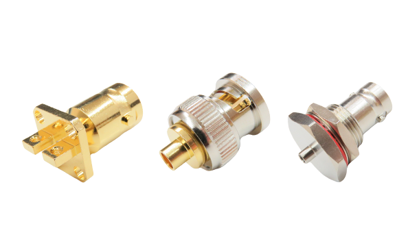
Common RF system interfaces include SMA, N, 2.92mm, 2.4mm, BNC, TNC, and others. Microwave adapters facilitate transition between these interfaces, preventing equipment incompatibility due to connector mismatches.
- Facilitating Frequency and Interface Transition (Legacy to Modern Compatibility)
As technology evolves, new interfaces like V (1.85 mm) and W (1.0 mm) emerged. Microwave adapters enable compatibility between legacy test equipment and modern high frequency modules, extending equipment lifespan and reducing overall system upgrade costs.
- Signal Integrity Preservation
High quality microwave adapters effectively control VSWR (reflection), insertion loss, ensuring signals remain undistorted and undiminished during transmission. This is particularly critical in GHz-level high frequency applications.
- Enhanced Impedance Matching
Microwave adapters maintain 50Ω or 75Ω impedance matching within the system, reducing return loss and enhancing overall system performance through proper design and precision manufacturing.
- Flexible Test Configuration
Microwave adapters enable rapid, flexible interconnection between various interfaces, supporting diverse test setups and reducing equipment changeover and configuration time in R&D and testing environments.
- System Integration Support
Microwave adapters enable seamless combination of modules or subsystems from different suppliers, helping to shorten design cycles and development time during system integration.
- Cost-Effective Maintenance
Using adapters avoids the need to replace entire test lines or equipment. Simply employing the appropriate adapter completes the conversion, offering significant cost efficiency.
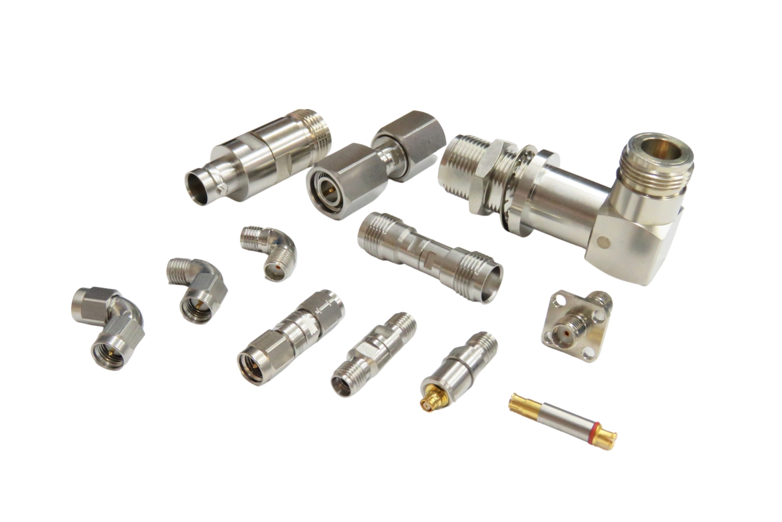
Microwave Adapter Types and Application Scenarios
Common microwave adapter types and application selection guidelines are as follows.
- Classification by Microwave Adapter Interface
|
Type
|
Description
|
Applicable Range
|
|
SMA to N
|
Common for low-to-mid-frequency conversion (DC~18 GHz) Significant size difference between the two connectors. |
Test instruments and
antenna modules |
|
SMA to 2.92mm (K)
|
High-frequency adapters (DC ~40 GHz)
Similar in size to SMA but capable of high frequency. |
Precision testing,
high-speed module interface |
|
SMA to 2.4mm/1.85mm
|
Ultra-high-frequency adapters
Supports 50 to 67 GHz frequency range. |
Millimeter-wave applications, advanced radar or satellite systems |
|
BNC to SMA
|
BNC is a low-frequency (<4 GHz) adapter.
SMA is a common connector for mid-to-high frequencies. |
General electronic testing,
communication system transition interface |
|
TNC to SMA
|
Used for outdoor waterproof equipment and indoor test equipment. |
Communication base stations, wireless network equipment |
- Classification by Gender of Microwave Adapter
|
Type
|
Description
|
|
Plug to Jack
(Male to Female)
|
The most common type, used for standard connections. |
|
Jack to Jack
Plug to Plug
|
Used for extension or special testing requirements e.g., inline connections. |
- Classification of Microwave Adapters by Product Perspective and Structure
|
Type
|
Description
|
Applicaiton Scenario
|
|
Straight
Adapter
|
Standard straight-through connection. |
Suitable for most applications. |
|
Right Angle Adapter
|
For use in space-constrained environments. |
Compact modules, internal cabinet wiring. |
|
Bulkhead
Adapter
|
Mountable on chassis or panel walls. |
Test panels, chamber structures. |
|
Panel Mount
Adapter
|
Mounted on test or equipment panels. |
For instrument panel adapter holes. |
How to Select the Appropriate Microwave Adapter?
- Based on Frequency Requirements
- For applications below 18 GHz, such as general RF testing or commercial communications, traditional microwave adapters like SMA or N-type can be selected.
- For applications at 26.5 GHz, 40 GHz, 50 GHz, or 67 GHz, select high frequency microwave adapters such as 2.92mm (K), 2.4mm, 1.85mm (V), or 1.0mm (W).
- Consider Interface Pairing
- Confirm the connector types (interface and gender) used by both end devices and select the corresponding adapter.
- For example, if the device uses a SMA plug as well as the test lead is a 2.92mm jack, the selection would be SMA jack to 2.92mm plug adapter.
- Based on Physical Space Requirements
- For confined spaces, choose right-angle adapters. For board penetration or panel mounting, select bulkhead/panel mount styles.
- Select High Quality Adapters to Maintain Signal Integrity
- For high frequency (>26.5 GHz) adapters, prioritize low insertion loss and low VSWR. Selecting precision adapters minimizes signal reflection and instability.
- Avoid Excessive Adapter Cascading
- Each Microwave Adapter introduces additional loss. Directly select the required interface adapter to avoid multi-stage cascading.
Microwave Adapter Performance Parameters
Key Performance Indicators for Microwave Adapters are as below.
|
Performance
Metric
|
Description
|
Evaluation Point/Impact
|
|
Insertion Loss
|
Energy loss incurred when signals pass through connectors, measured in dB. Typically, lower values are preferable (<0.1 dB is ideal). |
High loss causes signal attenuation, impacting system efficiency and sensing sensitivity. |
|
Return Loss
|
The ratio of reflected energy, measured in dB. Higher values indicate less reflection (>20 dB is ideal). |
Indicates impedance matching quality, preventing signal reflections that disrupt system stability |
|
VSWR
|
Voltage Standing Wave Ratio, ideal value is 1.0:1, common specifications are <1.2 or <1.3. |
Correlated with return loss, directly reflects impedance matching effectiveness. |
|
Opertating
Frequency
Range
|
The frequency range over which the adapter operates stably, e.g., DC–18 GHz, DC–40 GHz, DC–67 GHz. |
Must match the frequency bands used by the application system e.g., >50 GHz for millimeter-wave radar. |
|
Characterstics
Impedance
|
Typically 50 Ω or 75 Ω must match the system. |
Mismatch causes reflections and signal distortion. |
|
Impedance
Consistency
|
Internal structure of the adapter must maintain stable impedance, mechanical errors must not cause abrupt impedance changes. |
Affects high frequency signal integrity and phase stability. |
|
Dielectric
Withstanding
Voltage
|
The maximum voltage an adapter can withstand without breakdown, typically ranging from hundreds to thousands of Vrms. |
Critical for safety in high power or high voltage applications. |
|
Power
Handling
|
The maximum continuous power it can handle, dependent on frequency and temperature rise (e.g., 10W, 50W, 100W). |
Requires special attention in high power systems like radar or transmitters. |
|
Phase
Stability
|
Requires minimal phase error for phase-sensitive applications e.g., phased array antennas. |
Requires special attention in high and low temperature environments or for military specifications. |
|
Thermal
Stability
|
Frequency response and mechanical dimensions should not exhibit significant variation with temperature. |
Special attention is required for high-temperature/low-temperature environments or military specifications. |
|
Durability
|
Mating cycles (e.g., >500 cycles), structural strength, corrosion resistance plating materials such as gold, nickel, etc. |
Affects long-term reliability, critical for test equipment or industrial settings. |
|
Structure and Gender Types
|
Plug/Jack, Straight/Right-Angle, Bulkhead, Panel Mount, etc. |
Impact on actual assembly and spatial compatibility. |
Application Evaluation Recommendations for Personnel Requiring Microwave Adapters.
Focus on frequency, insertion loss, phase, and impedance matching. Exercise particular caution in high-frequency (>26.5 GHz) or low-loss applications.
- Quality Assurance/Quality Engineers
Prioritize specification consistency, electrical test results (VSWR/RL), plating quality, and durability test reports.
Ensure product model-specific frequency ratings, interface configurations, RoHS/REACH compliance, supplier certifications (e.g., ISO9001/AS9100), delivery schedules, and post-sales support.
Microwave Adapter of Huang Liang Technologies is engineered for Future Technologies
Huang Liang Technologies excels in four key points, technology, quality, production capacity/lead time, and application support.
- High Frequency Performance Control Capability
- Complete Product Lineup
- Simulation and Matching Capabilities
- Mating Durability and Structural Reliability Testing
- Customization Capabilities
- ISO 9001 Certification
- RoHS / REACH Compliance
- Reliability Test Reports
- Traceability
- Production Capacity and Delivery Capability
- Stable Supply Capability
- Fast Lead Times
- Provide 3D CAD / Electrical Models
- RF Design Consulting Capabilities
- Rapid Sample Support
Conclusion
Microwave adapters are widely used connectors in communication and wireless technologies, offering flexible connection solutions for diverse devices. They simplify and streamline connections between equipment and devices under test. These adapters play a vital role across various applications, providing users with enhanced flexibility. Huang Liang Technologies is a specialized manufacturer of RF microwave connectors/microwave adapters, featuring the exclusive Uni-adapter compatible with various adapter series. We also offer dedicated customization solutions. We provide comprehensive one-stop services including initial design, product simulation, assembly operations, and electrical analysis to deliver optimal solutions. For further product inquiries, please
contact us right away.